Input and Output Experiments and Weekly Readings
Electronics Lab
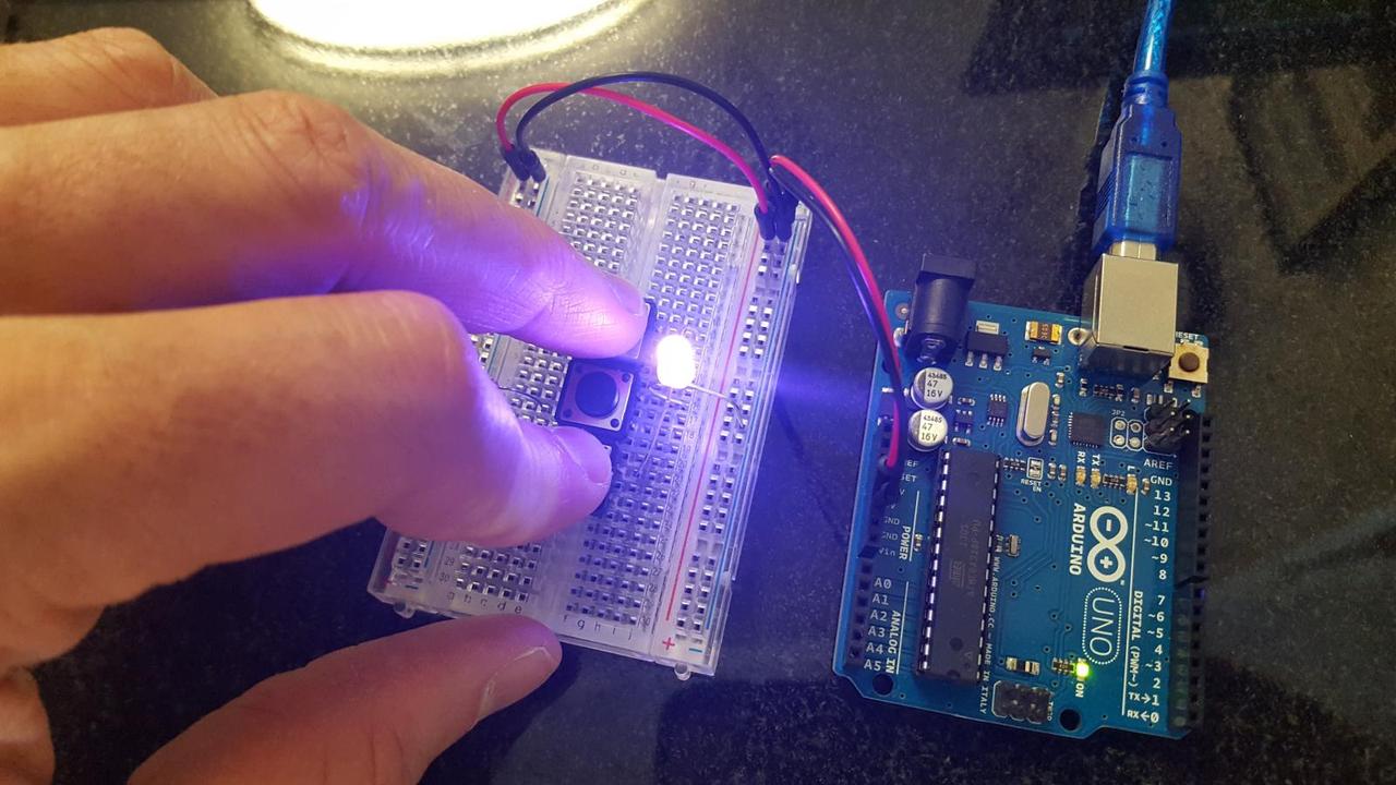
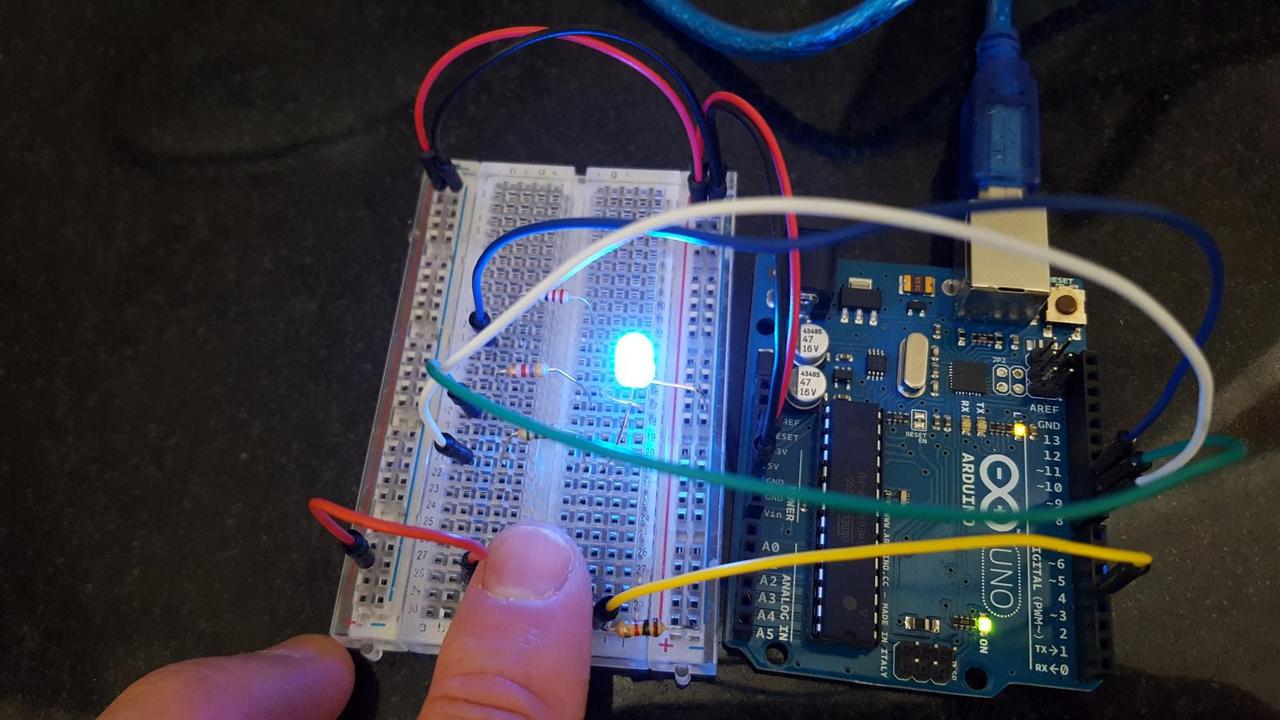
Our assignment for this week was to create something using digital or analog inputs and outputs. The circuit I created will light up a 3-color LED with a new randomly selected color when a button is pressed.
Here is a photo of the completed device:
And a schematic of the circuit:
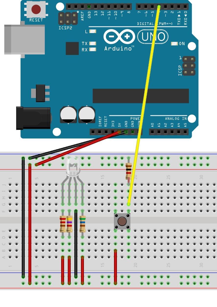
The Arduino uses digital input to detect when the button is pressed and released. It picks random RGB values and outputs analog values to light up the 3 color LED in that color. Observe I am using the 3 resistor values I calibrated for last week's assignment to make the LED's 3 colors balance out.