Experiments With Sound
Upcycling a Speaker
A year ago someone gave me a birthday card that played a song when the card was opened. As I was interested in learning more about circuits, I took apart the card and saved the electrical components for a time when I could dissect them and learn more about how they work. Last week we learned about sound in our physical computing class, so it seemed like a good time to put the inexpensive speaker to good use.
To upcycle the speaker I rewired it to give it red and black wires for the speaker's positive and negative terminals and a header pin to go into a breadboard. I also built a 3D printed case as an assignment for my 3D printing class.
It looks nice but I need to think about how to make this work with an Arduino. This isn't an Arduino provided part so it isn't immediately clear how to use this. If I put too much current through it I could potentially blow out the speaker. If the Arduino can't output enough current the speaker's sound might be inaudible. Will this work at all?
The rear of the speaker has 8 Ω 0.25 W printed on it. This tells me the speaker's resistance and maximum power output. I can use this information to figure out how to use the speaker with an Arduino.
Presumably I need to wire the speaker in series with a resistor of some unknown size. That circuit will look like this:
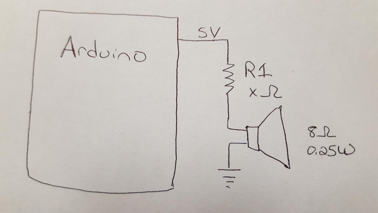
I need to figure out the resistance of resistor R1 that ensures the electrical power going through the speaker does not exceed 0.25 W. Using the circuit diagram and the below equations, I can figure out if I can safely use this speaker with my Arduino.
The total resistance through the circuit is \(x + 8\) and the maximum voltage of a digital output pin is 5V. Using \(V = I \cdot R\) I can calculate the current as:
Next I need to calculate the voltage difference across the speaker, \(V_s\). The speaker's resistance is 8 Ω (which I confirmed with a multimeter), so using the same equation and my calculation for \(I\), I can solve for \(V_s\):
Using \(V_s\) and \(I\) I can calculate the electrical power going through the speaker with \(W = V \cdot I\).
The speaker is rated for 0.25 Watts, which is an upper limit on the amount of electrical power that should go through the speaker.
What is the minimum amount of resistance \(x\) necessary to keep \(W_s < 0.25\)? Using basic algebra and the quadratic formula I can calculate \(x \cong 21\). Therefore, the resistor I add to the circuit should be at least 21 Ω.
That seems kind of low to me. With a resistor of that size, what is the total amount of current going through the circuit? Using our equations we can calculate that as:
The current is 0.172 Amps, or 172 mA. That's more than the maximum amount of current that the Arduino's Atmel ATmega328P can safely output on a pin. The limit is 40 mA, and ideally my circuit is not actually near the limit. Therefore, a 21 Ω resistor is not large enough for this circuit. The necessary resistor size \(x_2\) is:
I obtained a 150 Ω resistor from the shop. If I use that resistor, how much current will go through the circuit? Substituting that into my equation for \(I\), I get 32 mA. That is a reasonable amount that will not damage the board or the speaker. This current means the wattage used by the speaker is:
That's pretty small, and about 3% of what the speaker is capable of. Nevertheless, when I build the circuit and use it, I can hear a tone from the speaker. Therefore, I was able to successfully upcycle a speaker from a greeting card with an Arduino.
Questions
Why is it that the small circuit in a Hallmark card can play an actual song with its speaker but an Arduino can't play more than one pitch at a time? The card's circuit must be specially designed to modulate voltage in a particular way. How does it work?
Simultaneous Pitches
In class Tom told us that an Arduino can only generate a single tone at a time. He said that it wasn't possible to generate two simultaneous pitches at the same time and that attempts to switch back and forth between them resulted in very bad sound quality.
In class he also talked about servos and how the Arduino's servo code worked. His explanation suggested to me that there should be a way to generate two simultaneous pitches. All of my initial ideas for doing this that I thought of during class were failures, but I learned a lot about Arduinos in the process of trying things out. I was intrigued by sound generation and stuck with it. Eventually I came up with a viable idea. I now claim that I can create a circuit that generates two proper simultaneous pitches. There are some limitations, but it definitely does what I say it does.
I quickly realized the only way this could possibly work is with true analog output. The Arduino's analogWrite function uses Pulse Width Modulation (PWM). This feature will oscillate a digital pin from HIGH to LOW on a set frequency with the analogWrite value used to determine the portion of the time the pin is at HIGH or LOW. The end result is the average voltage over time matches the analogWrite parameter but at any instance of time the voltage can only be HIGH or LOW.
There are a few ways to get a true analog output from an Arduino. The way that I used that worked was to build a R-2R Resistor Ladder. Specifically, I built a 2-bit digital-to-analog converter using a bunch of resistors that all have the same resistance. The end result is I can use two digital pins to manufacture a voltage that can be at one of four voltage levels between LOW and HIGH. I can use this to achieve my desired result.
The completed circuit is below. There are two buttons that control each of the two tones. Pressing both buttons at the same time generates both tones.
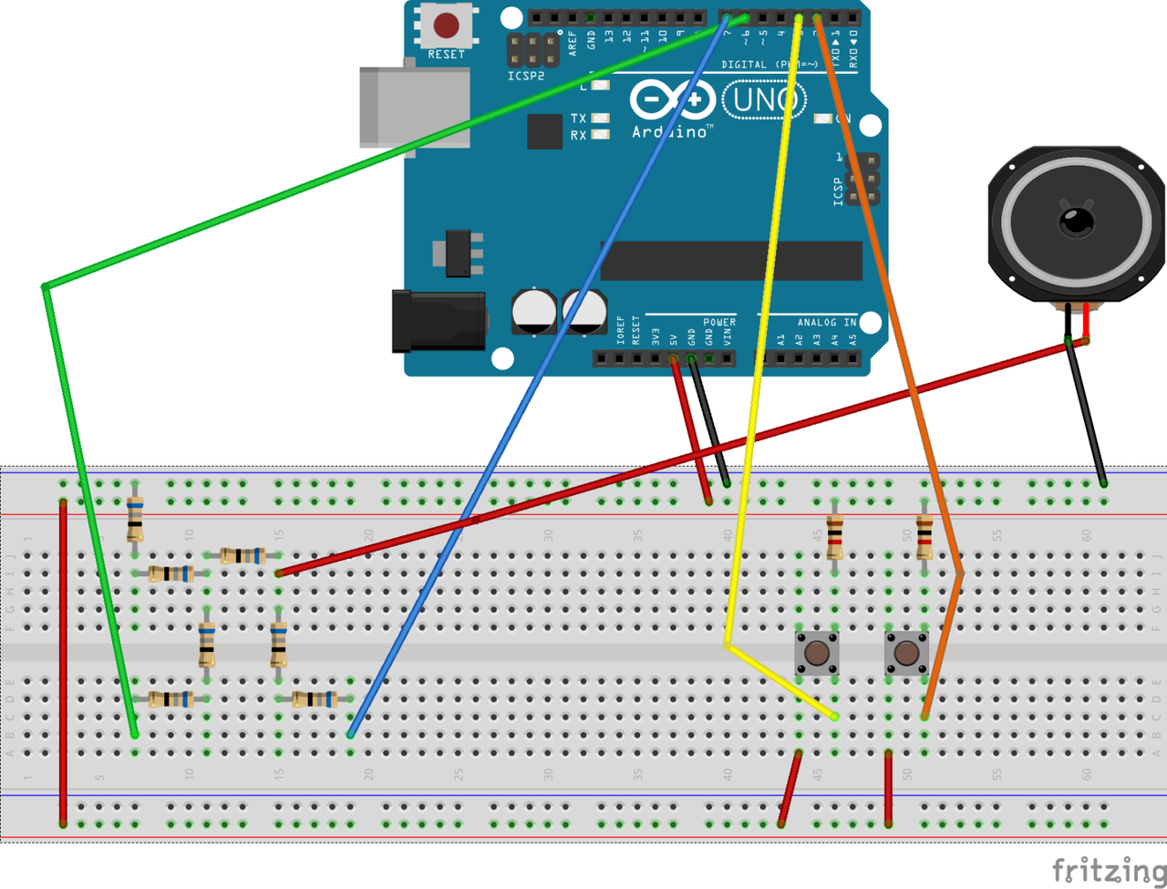
The circuit by itself isn't enough. The Arduino code needs to be carefully written to allow it to flip the bits at precise intervals. I had to do some performance testing to measure how fast the digitalWrite function is (4 microseconds), which matters a great deal for this application. Nothing is instant with computers, and sometimes that matters.
The relevant code is below.
const int FREQ0 = 523;
const int FREQ1 = 1046;

void setup() {
  // configure input/output pins...

  // calculate the number of microseconds between HIGH/LOW flips in the waveform
  pause0 = 1000000 / (2 * FREQ0);
  pause1 = 1000000 / (2 * FREQ1);
}
Please forgive the following terse code. In this case making my code more readable might also make it slower, ruining the end result. I added comments to attempt to explain it.
void loop() {
  unsigned long t = micros();

  // advance to the next time we have to flip a bit
  int pause = min(pause0 - t % pause0, pause1 - t % pause1);
  delayMicroseconds(pause);
  t += pause;

  // if a button is being pressed, determine if its wave is HIGH or LOW based on an
  // odd or even number of elapsed pause delays
  bool wave0 = button0 && (t / pause0 % 2);
  bool wave1 = button1 && (t / pause1 % 2);

  // set digital pin 0 to HIGH if one of wave0 or wave1 is HIGH
  // set digital pin 1 to HIGH if both wave0 and wave1 is HIGH
  // Note: HIGH == true
  // Note: digital pin 0 and 1 are never set to HIGH at the same time, but they could be.
  digitalWrite(SPEAKER_PIN_0, wave0 ^ wave1);
  digitalWrite(SPEAKER_PIN_1, wave0 & wave1);

  // read both button pins and compare values to HIGH to see if they are being pressed
  button0 = digitalRead(BUTTON_PIN_0) == HIGH;
  button1 = digitalRead(BUTTON_PIN_1) == HIGH;
}
There are some limitations on the two chosen frequencies. In the example code above I am using C5 and C6, which are two notes that are one octave apart. This isn't a requirement but it seems to help. I haven't fully figured out the bounds of the limitations but I know it has to do with the programming being late for a necessary time to flip a bit because of the time it takes to execute digitalRead and digitalWrite.
Anyhow, here's a video of the circuit in action:
It works!!!
Comments