Finishing a custom keyboard at home (Part 3)
Almost done with the custom keyboard!
Refer to (part 1) and (part 2) if you have not read them already.
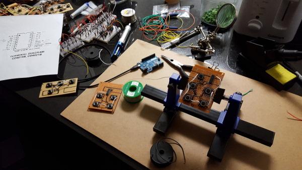
I finally built up the courage to attempt the actual assembly. This part was very difficult and it took me a long time to figure out something that made sense and seemed achievable. There are so many buttons...how am I supposed to organize the buttons, the wires, the shift registers, and the resistors?
I started by soldering the buttons into place in their correct locations on each circuit-board along with resistors and wires for power and ground. Each circuit-board connected the power and ground wires to each other so I only had to add two wires from one board to the next to power the buttons.
Then I divided up the circuit-boards into "key regions." Each region is controlled by shift registers in that region. The circuit-boards in each region share power and ground with each other.
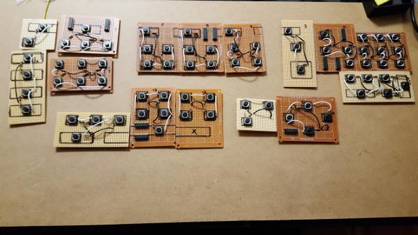
I completed the soldering for each key region and tested them with an Arduino to verify that the buttons worked. Then I linked the regions together, connecting the shift registers' data, latch, and clock wires and adding power and ground. Everything was attached to the acrylic using velcro to keep the circuit-boards in the proper place.
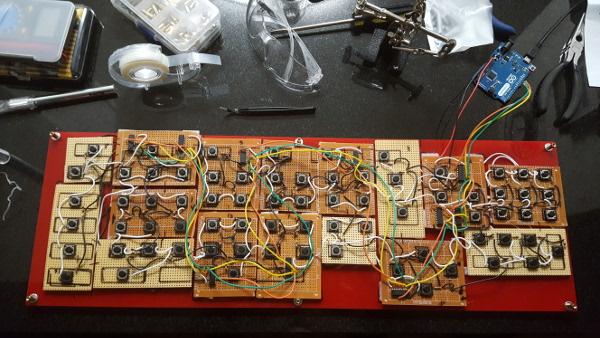
Clearly that's a messy collection of wires, and the solder joints on the other side aren't any better. There's about 50 ft of wire on both sides of the circuit-boards and hundreds of solder joints. Nevertheless, the buttons work like they're supposed to. I added some scotch tape to keep the wires under control and assembled the keyboard buttons.
The keys are multi-colored using a collection of Sharpie markers I bought for this purpose. When I met with Shaniqua we came up with the idea of using colors to make the keys easier to find. The numbers and vowels are Shaniqua's favorite color, pink.
The project isn't quite complete. A few of the keys need to be sandpapered so they slide better. Shaniqua wanted the keyboard to be tilted up instead of flat so I need to come up with a way to angle it up. Also I need to do some programming to make the action buttons at the top of the keyboard do something. All of these things are easily achievable. Hey, I've made it this far!
There are some things about this project that didn't go so well. The arrangement of the buttons and wires was hard to manage and caused many problems and mistakes. I did it that way because the only way I understood how to build this with the resources I had available to me was to have all of the components together on a single plane of circuit-boards. On the other hand, I learned a lot about good and bad solder joints and I got a lot of practice diagnosing problems with a multimeter and de-soldering. The electronics work but they caused a lot of late nights and stress. In the future I will be much more disciplined about how I solder connections in circuits.
There are also some problems with the button design. There are no comma or question mark keys, something that most users would certainly miss. The carat, tilda and second asterisk keys are less important and should be replaced with other characters or eliminated entirely.
Comments